|
I wanted a project car that would be interesting to build, quick and fun to drive, I had long thought of a clubman, but after
the GFC, finances were looking a bit slim, I already had a Fiat X1/9 road car and I decided on a light weight X1/9 I could use
for track days. I was inspired by the Abarth X1/9 Prototipo, but I wanted to keep it more original looking, and still with the
1500 SOHC engine. To fit the bill, I would have to get rid of any excess weight, and make as much power as my budget would
allow without going to special race components.
Another SA Fiat club member had a late model Bertone X1/9 rolling chassis, with engine, for sale and a deal was done. Apart
from the fact that the gearbox had already been scavenged, this was an almost ideal starting point, it was cheap because there
was no interior, no seats, carpet, dash, instruments, door window glass or regulators, no radiator or bumpers, all of which I
wouldn’t need anyway. It had very rusty door skins, ideal to be replaced with aluminium ones, and minor damage to the front left
corner, but the main shell was pretty good apart from rust in the tops of the sills and around the headlights. The rust in the
sills was cut out and new steel welded in.
|
|

|
|
Weight reduction was the first target. All the sound deadening was scraped off the underbody. Front impact absorbing bumper bar
mounts were removed by drilling out the large 8mm spot welds, the rears are different, so they were attacked with an angle
grinder to remove as much as was practical. Jacking points were cut off and replaced with low profile aluminium pads. Also
discarded were heater, aircon, horns and radiator fan. The leaking steel coolant pipes running the length of the car were replaced
with aluminium ones (one job that was a lot harder than expected, the only tube available of 35mm diameter was 1.3mm wall high
strength 6061-T6, so the ends that needed to have bends are of a softer grade and thicker wall, the ID slides over the OD of
the straight sections, but even then they split when bent on a pipe bender, so they had to be annealed before bending, then
joined on after). The panel behind the radiator was mostly cut out, as I wanted the hot air to vent through the bonnet for
better air flow.
|
|

|
|
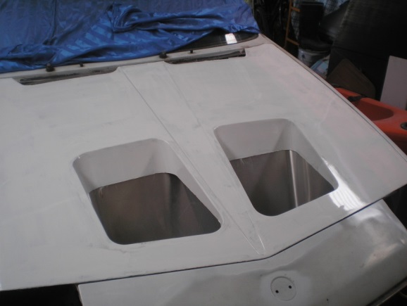
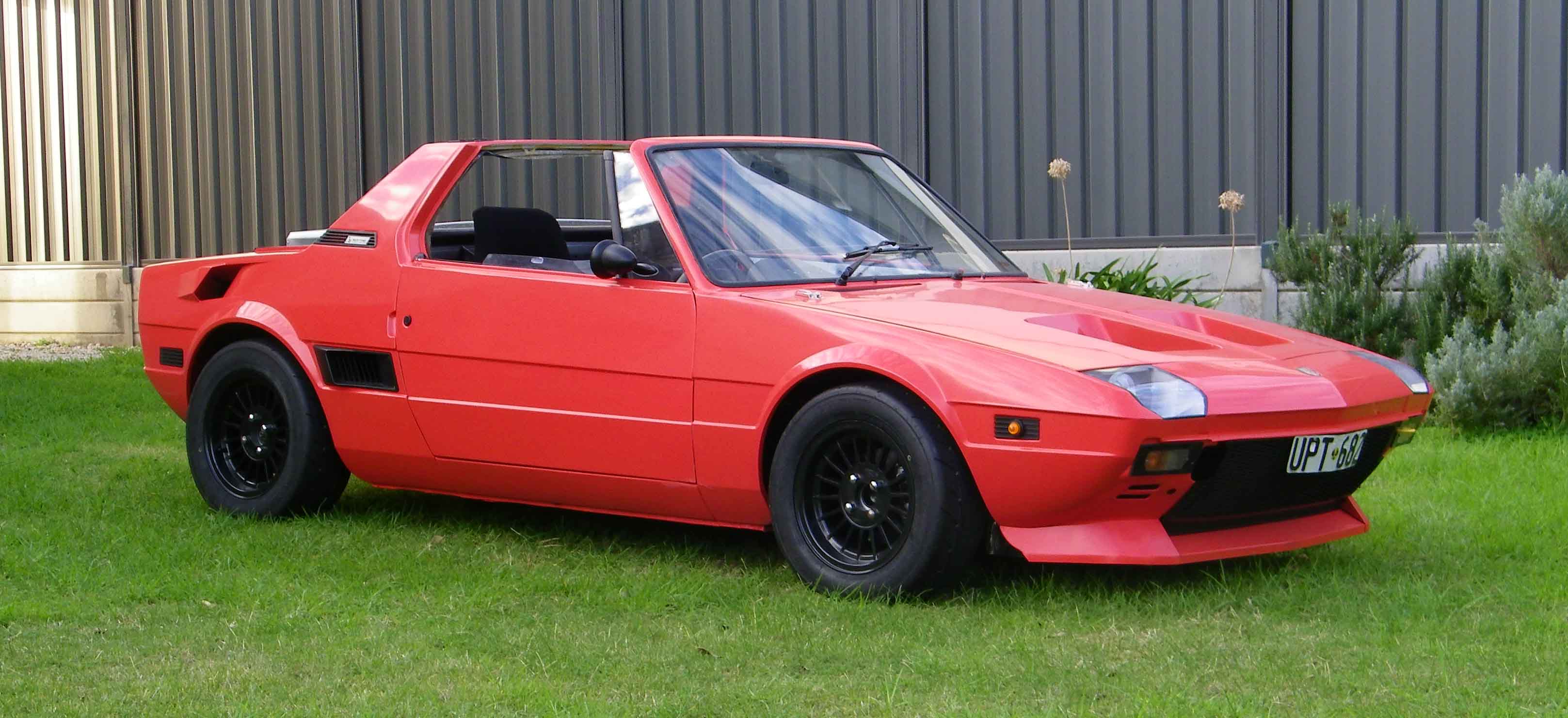
An aluminium radiator (Punto racing type) is used with an aluminium mounting bracket, and ducting to bonnet vents. The pop up
headlights and motors were replaced with 90mm projector headlamps, Hella style, in thin aluminium housings with custom polycarbonate
covers. Custom fibreglass bonnet made using original one as the basis for the mould, same for the rear boot lid, both with
aluminium hinges.
|
|
|
|
Fibreglass racing style buckets seats are bolted straight to the floor. The old rusty door skins were removed, along with
the intrusion bars, plus many large holes cut in the frame, a thick wall aluminium tube intrusion bar was fitted to the
drivers side, and then aluminium skins fabricated and bonded and riveted to the frames, a simple pushbutton door release
was used. Polycarbonate door windows were cut to shape, and heated in the BBQ to form the curvature while clamped to standard
glass windows. The steel window frames/guides were replaced with aluminium channel and curved to the right shape, there
is no lifting mechanism, just lift by hand and lock in the up position with a knob. The standard fuel tank is replaced
with a custom fabricated aluminium one of 14 litres in the same place, it’s tall and narrow with a 750ml sump at the bottom,
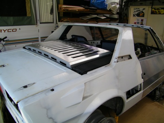
just enough with a bit to spare for 5 or so laps on a long track to carry minimum weight and no fuel surge. There is a custom
made fabricated aluminium series 1 style engine cover, with extra ventilation, aluminium hinges, simple flat spring catch
and wood dowel prop to hold open. (As does boot and bonnet). The boot floor was also cut out and replaced with aluminium,
complete with pressed ribbing, and riveted and bonded in place. There is also an alloy front spoiler and flat undertray
between the spoiler and the car floor/footwells. All this attention to detail was vindicated when I took it to the weigh
bridge after the car hit the road, weight is down to 690kg (no roof or spare wheel) from 930-950kg.
|
|

|
|
Transmission
In between jobs, I got hold of a replacement 5 speed gearbox, well, 3 actually. Another Fiat SA club member had 2 broken gearboxes
that he was going to make one good one from, he was good enough to sell them to me at the right price. One box had a cracked case
but the internals were mostly good, the other one had had a major internal problem, and many gears had broken teeth. One hesitation
I had was that I had never worked on a gearbox of any kind before, and these were just boxes of bits, but hey, how hard could it be?
Before starting this project both Peter Bartold and John Black of the Victorian Fiat club had been kind enough to give me pointers
on things they have found to work well in their respective X1/9 race cars, and one thing was to use the main gearset from a Fiat
Regata 100S 5 speed gearbox and the X1/9 4.077:1 final drive, to give a close ratio gear set. (The Regata has a 3.21:1 final drive
ratio). I was lucky enough to find one at a local wreckers, so this was pulled to bits and the main shaft and gearset used in my
rebuilt box. Some of the bearings were a bit noisy, so I thought it best to replace them all, but I had trouble finding a replacement
for one of the large main bearings, SKF 616034A, this I eventually got from ABF Bearings in The Netherlands for only 5.35 Eur. Also,
the sleeve that 5th gear runs on on the lay shaft was worn slightly, and I couldn’t find a replacement, so I used the 5th gearset
from the X1/9 box, which is an overdrive ratio. The end result is a very low 1st gear, then 2nd, 3rd and 4th close together, then
a jump to 5th. But at least this way I shouldn’t run out of revs in 5th on long straights like Phillip Island when using my 185/60
13 tyres. I estimate top speed of about 205kph, at 7,200 revs, which is just over peak power. One drawback with the Regata main
shaft is that the spline on the clutch end has to be shortened by 19mm for clearance in the flywheel, angle grinder does the job.
The length of spline on the shaft also limits the clutch plate travel, so I had to bore out the spline in the clutch plate a bit
so it would fully release. On the other side, I also welded a band of an old spline of the same length that was bored out, to
maintain the same total spline length for strength. Some say you can just reverse the clutch plate to avoid all this, but it
didn’t work on mine, the friction plate was fouling on the pressure plate.
|
|
|
|
Engine
Most of my research for engine mods was done on the internet, I don’t know how I could have done this project without it. Guy
Croft Race Engines is a well known developer of Fiat Twin cam engines, but also SOHC and other makes now, his site was very
useful, there are forums and posts by Guy, but it looks like you now have to pay to join. The Xweb and turbo124 forums also
had lots of useful info, the PBS book Project X1/9 is an interesting read but not overly useful for my project.
My Bertone came complete with the standard Bosch fuel injection, but it is very limited for performance modifications, (plus
I am old school and like the idea of twin carbs) so the only part that was retained was the electronic ignition. The engine
was still in quite good condition, but it would still need new pistons and a rebore. I bought a set of 86.6mm Borgo US style
pistons with the large valve recesses, the inlet valve cutout was enlarged even more to clear the 39.5mm Fiat Tipo inlet
valves. Total Seal Gapless 2nd rings were used (part no. S9316 +10 oversize 86.5mm nom.) The block was bored and honed for .04mm
clearance on the pistons, and decked 0.5mm to make the block level with the pistons. The crank still looked good but just to
be sure was ground to .010” undersize and new bearings were ordered. The flywheel was lightened by machining the engine side
near outer dia and drilling 28, 13mm dia holes to 10mm deep around the outer edge on the clutch side. This reduced the weight
from 7.1kg to 5.8kg. Crank balanced and then flywheel fitted and balanced. The pistons, gudgeon pins and con rods were all
balanced to within ˝ a gram.
A sump oil control plate/windage tray was fitted. I considered the US made windage trays, but I can’t see how they can control
oil surge during cornering, there are gaps at the ends to let the oil flow back, which also means the oil can flow out,
especially the left side during RH corners. So I made a nearly horizontal one that stops the oil flowing past the shallow
LH end and upwards, it starts about in line with the oil pickup and fits close to the sides and the shallow end, but slopes
back to the middle for draining. It also has another part that fits at the RH end and very close around the pump body, the
drain from the breather goes through it and a small hole in it for the dipstick. I also lowered the oil pump pickup a few mm
by modifying the plate on the intake to get every last bit of oil in the pan. It seems to work ok, I have had no oil pressure
problems so far at Mallala or Winton race tracks, the only problem I have is that if I over fill the sump by ˝ a litre like
I used to, it pumps it out the breather into the catch tank, probably because the trays are not long enough to retain the
extra volume.
The Bertone head has a large recess 2mm deep right out to the full bore dia, the face would have to be machined right back
to get rid of it and to increase the compression ratio to around 11:1 in the process. These heads have 14 head bolts, the
usual 10, 10mm ones, plus 4 small 8mm ones on the spark plug side, damn hard to get the head off till these were found.
The head was worked for improved flow and performance. The inlet seats were replaced to suit the larger 39.5mm Tipo valves,
(valves ground with 30 degree back cut), standard (new) exhaust valves used, all seats cut to 3 angles after porting. Bronze
valve guides were pressed in, (from Precision International, made by Jones & Davey in Mannum, SA) although they needed
reworking, a step for the seal, and reaming after fitting to get correct clearance on stem. An air die grinder with carbide
burrs and abrasive drums was used for porting. The exhaust ports were not enlarged, just smoothed out a bit. The inlet ports
were enlarged to 32mm and short side radius increased slightly, (this was too big, don’t remove more than about 1mm from
the port roof as it is only about 4mm thick, if too thin it can leak coolant through porosity in the casting, see text later).
Inlet ports tapered out to 33mm at manifold to match manifold ports (manifold located with dowels in head to align exactly,
gasket also needs enlarging and matching). Material removed from next to valve guides to improve flow and throat opened out
to 33.5 to match new seats. The combustion chamber needs deshrouding around the larger inlet valves, it can be cut back at
a slight angle so when the valve is open there is good clearance between the valve head and the casting for good flow. Make
sure you don’t cut into the head gasket seating area. The combustion chambers volumes were measured and material removed to
make them all the same. After the head was faced to get the desired compression ratio, all the volumes were checked again,
and tweaked as required, to achieve a compression ratio of 11:1. All sharp edges were removed in the combustion chamber. When
assembled, a coat of Permatex copper spray gasket sealant was used on both sides and the head torqued to the standard angle
method using new head bolts. Then retorqued a further 20 degrees or so to 60 ft-lbs after a few hundred kms. Just out of
interest, I recently came across Fiat Service Letter 100-18 at www.artigue.com/fiat-service-letters/ from 1981 that specifies
retorqueing procedure during pre-delivery inspection or specified intervals. This specifies re-torqueing in 2 stages, 1st a
further 60 degrees, then another 30 degrees. I haven’t tried this as yet.
With a high lift cam, the base circle of the cam is reduced in diameter, this requires the use of either very thick tappet
shims, top hats on the valve stems, or machining the mating face of the cam box to head. I chose the latter, and had 1 mm
machined from the cam box and it was assembled without a gasket, just using silicone.
One side effect of lowering the cam box and shaving the head so much is you run out of adjustment of the timing belt, you
can overcome this by using a 1300 tensioner and pulley with its larger diameter.
Valve springs used were US made Isky springs that seemed to work ok, but when I had to change heads, (more later) I found
that with the dimensions or tolerances with the replacement head, and my high lift cam, I was getting spring bind at full
compression. One solution to fix this was to pull the head apart again and get the spring seats machined lower, but this
would have meant a lower pressure to seat the valve, and to keep in contact with the cam. My solution was to buy a new set
of springs from Performance Springs Australia, not only do they have better clearance to eliminate the coil bind, but they
have a higher spring rate and pressure in keeping with the specifications of the cam manufacturer.
The cam chosen was a Piper FIAX19 BP300 Rally as recommended by Guy Croft and used by others on his forum with good results
for its midrange torque and good top end power, with max power around 7,300rpm. Claimed power band 3,000 to 7800 rpm, lift
is 11.18mm, timing 39-71-71-39. I used an aluminium alloy timing pulley and auxiliary shaft pulley. The timing pulley has
a new dowel hole to get the cam timing spot on to the cam manufacturer’s recommendation.
|
|


|
|
Carburettors
I wanted to use twin Weber DCOEs to get the most power, but should I use 40s or 45s? The graphs in the Weber manuals suggest
a main choke size of around 36mm for 7,300 rpm and 1500cc, and the general advice is not to go too big with twins on a
small engine, especially if you want good midrange torque. As 40 DCOEs will accept chokes up to 36mm they seemed like a
good choice. I found a pair on Ebay (from Germany of all places) for a good price, and even the postage was ok. I also
ordered a set of 4 new 36mm chokes from the UK. On arrival I discovered that 40 DCOEs have a different style auxiliary
venturi holder body to 45s, and the inside diameter of them is only 37mm, that’s the entry into the carby, just 1mm more
than my chokes diameter. So how will the venturi work properly to speed up the air flow? After further research I discovered
that no one recommends going bigger than 34mm chokes in 40 DCOEs. Seeing as I already had the parts, I decided to bore out
the auxiliary venturi holder to 40mm in an attempt to get the main venturi (36 choke) work properly.
As most X1/9 owners will know, you have to cut out at least part of the cross member behind the engine to clear DCOEs. I
cut the minimum I had to and retained the original appearance, and re welded sheet steel to maintain the strength, but it’s
a bit too close, I have to remove the carbies to take the top off to adjust float levels. At least I can change the jets
without going to that much trouble. It would probably be better to cut the original cross member out altogether and weld in
a piece of round or square tube instead. That would also give more options for fitting air cleaners. I have made an aluminium
plenum that has a fuel resistant foam rubber sheet that is a close fit over the carbie tuned length ram tubes to locate it, and
also foam rubber pads between the plenum and the boot floor to support it, the right hand side clamps to the K & N pod air filter
housing with a flexible duct made of wet suit material. Cold air intake is through a duct cut into the right hand rear guard
just above and behind the wheel arch, shaped for good air flow and minimum protrusion.
Fuel pump is a Facet cylindrical electronic pump, low pressure, high flow, 477060E, 2.75 – 4 psi, 34 US-GPH max, typically
10 GPH @ 2 psi. For safety, it is wired to the oil pressure warning light with a relay so that if the engine stops, the
fuel pump stops. There is also a push button switch on the console to prime the carbies when the engine is not running if required.
|
|

|
|
Exhaust
The exhaust pipe lengths are from the Guy Croft web site. He has information from simulation and dyno testing that a well designed
4 into 2 into 1 extractor system can give better power and torque figures than a 4 into 1 system on the Fiat engine. I had bought
a 4 into 1 PBS style set of extractors, and the pipe length to the collector of 28 inches was too short for the ideal 4 into 1
system, but exactly right for the primary pipe length for 4 -2 - 1 for the X1/9 engine. So I cut the collector off and made
new collectors for 4 into 2, welded on 2 bends of 12-14 inches long for secondaries, then a 2 into 1 collector for the 2 inch
tail pipe. I wanted a long 4 inch diameter straight through muffler to make it quiet enough for noise restricted tracks, but
have minimal back pressure, but couldn’t find what I wanted. So I bought a length of perforated pipe and fibreglass packing and
made one 24 inches long with an aluminium skin, and finished it off with an aluminium final bend and exhaust tip.
Original water pump replaced with an electric Davies Craig one for good flow at all revs for optimum cooling and reduced power
loss. The pump takes the coolant from the thermostat housing and into a new coolant pipe that runs across the back of the engine
and into a plate where the old pump was. The pump runs continuously when the ignition is on, a standard thermostat is retained
to regulate the flow. As mentioned earlier, the radiator is an alloy Punto racing style, double pass crossflow, with inlet and
outlet both on the left. There is no fan fitted. The series 1 front grille has had the holes enlarged for better air flow. It
has run a bit hot on the track on a high 30’s day, but putting little air deflectors at the leading edge to the bonnet air vents
helped, I think the high air flow over the bonnet is slowing the air flow out of the radiator a bit.
The alternator was replaced with a small light weight 45 amp one from an early model Daihatsu Charade. Starter motor is a compact
gear reduction type, 25% less weight than original, (not the near 50% as advertised). The battery is a bike battery intended
for Honda Goldwings and Harleys, an SSB PowerSport AGM XR series RTX20-BS, 400CCA, 18Ah, 5.9Kg. This is less than half the weight
of a standard battery, but I would have liked to use the equivalent Lithium battery from the same manufacturer at only 1.7Kg,
for around $300, but they don’t recommend these for use in cars, even race cars, and reckon it may not last long. The ones they
did recommend were 2 or 3 times the price and I didn’t want to spend that much, I still think the cheaper 1.7Kg ones would be
ok, but it’s a lot of money to risk if it only lasts a year or so.
Along with the original Bosch electronic ignition module, I also retained the distributor. The plug leads were replaced with a set
of Eagle Eliminator 9mm ones, and plugs are colder than standard NGK BPR8ES.
|
|

|
|
Suspension and brakes
The brakes are standard X1/9 disks, standard front calipers, Fiat 125S (or 132) rear calipers with the larger 38mm pistons,
stainless braided lines and EBC Yellowstuff or Greenstuff pads, these look like they have overheated and are starting to crumble
around the edges. There are also brake ducts to the front calipers. The brakes work ok, but for hard braking tracks like Mallala
an upgrade would surely improve times by a small amount. Wheels are Performance 13” x 6” alloys painted in black enamel, with
8mm alloy spacers replacing the standard 4mm steel ones. Tyres are Toyo R888 185/60 13.
Suspension is pretty much original, but lowered about 30mm by cutting the coils 1 turn and squaring the ends again. The shorter
length and lighter overall car weight means they are effectively stiffer.
Strut mounting holes raisedThe original front struts lower mounting holes were raised 16mm by drilling new lower holes and welding
a piece of steel at the top for new holes, these top holes were moved inwards slightly to increase negative camber. This achieves
the desired lowering but still allows the springs to be retained at full suspension droop and not come loose. Later the front camber
was increased further by slotting the strut top mounting holes, it currently has about 2 ˝ degrees negative at the front and 3
degrees negative at the rear. Caster was increased from 3 to 3 ˝ degrees.
|
|

|
|
Body and interior
A new instrument pod was made to fit a Fiat 124BC tacho and speedo (still in mph), eyeball air vents were fitted at either
end, along with the original centre vent, the remainder of the bare steel body/dash was covered with 10mm foam rubber glued
on and then black felt. The centre console alloy panel houses 3 small gauges, a Fiat temp gauge and fuel gauge, and a
matching mechanical oil pressure gauge marked Olio, that I’ve had for about 30 years, it just needed a home. Also a master
switch and start button, and lights switch. The wiring was a challenge for a non-electrical guy. With all the cabin electrical
items previously removed and nothing labelled, I had to trace all the wiring from the fuse box (a big heavy one compared to
a series one X1/9), along with the help of about 10 pages of wiring diagrams. While I was at it, I removed as much of the
wiring as I could for the non-essential items I had discarded. About three weeks work.
The body is painted in X1/9 rosso arancio (171) acrylic, it’s cheap and easy to paint at home. The interior and underbody was
brush painted with a matt grey hardwearing urethane, KBS Rust Seal.
|
|

|
|
On the road
After about 5 years of work, it was time to hit the road for running-in and tuning. After about 200 km of fairly hard driving
to bed in the rings it was off to the dyno. Although the power figures were quite good, using Premium 98 ULP, 85.4 kW (114.5 hp)
and 125.2Nm (92.3 lb-ft) at the wheels, which works out to around 135 hp @ 6,900 rpm and 109 lb-ft @ 5,200 rpm at the engine
(assuming 15% losses), we couldn’t stop it from running rich in the midrange (11:1 A/F ratio) without going lean in the power
range, over 13:1 A/F (around 12.6 is ideal). We had to use ridiculously small air jets, the best compromise was with 138 main
jets, 100 air jets, using F9 emulsion tubes, 55F8 idle jets, 45 pump jets, and the 36 chokes. In the attempt to get the 36 mm
chokes to work efficiently, the mods to the auxiliary venturi bodies (see carby section) may have upset the air flow through
the 4.5 auxiliary venturi itself, possibly explaining why we had to use very small air jets, but I’m not sure. In hindsight,
I probably should have bought 45 DCOEs.
On the road, it pulls really hard in the mid range and at the top end, only problem was a stumble at progression from idle to
accelerating, which I can live with for track use. Over the next few days I noticed the coolant level kept dropping slightly,
further investigation revealed coolant was weeping through the roof of one inlet port. The head was removed and stripped and
taken to a head specialist for welding. This was unsuccessful as the casting was too thin thanks to opening the intake ports
out to 32mm and removing too much material from the roof of the port.
I had to get another head, the current one is a Regata 10 bolt head, and repeated all the head work, except with 30 to 31mm
intake ports while removing no more than 1 mm from the roof of the ports. This time I used a Nava Linea Sport HP3 racing head
gasket from Ricambi Tuning, Italy, 1.6mm, 1.45mm thick when compressed, (Spesso Racing also do one). This is slightly thicker
than the one used before, giving a compression ratio is about 10.7:1. (I also had to rebuild the bottom end and replace 2
broken pistons, but that’s another story)
I fitted an Innovate air fuel ratio gauge so I can further tune it on the road. I also fitted 34mm chokes to try to improve
the jetting. It didn’t make much difference. After many hours and kilometres of trial and error tuning to the air fuel ratio
gauge, including constant revs as well as the wide open throttle (WOT), I am pretty happy with the setup, 34 chokes, 4.5 aux
venturi, mains 135, airs 115, emulsion tubes F11, idle 45F9, pump jets 45, needle valves 180, pump back bleed 60, float level
8mm below aux venturi nozzle. The air fuel ratio is about 12:1 at constant cruise 2,500 – 3,500rpm, at WOT it’s 12:1 at 5,000rpm,
12.5:1 at 6,000 and 12.3:1 at 7,000rpm. On the track I will generally change up at 7,500, occasionally at 8,000 in 2nd gear.
It feels like it pulls just as hard as it did with 11:1 c/r but logic tells me it has probably dropped a few hp, but who knows,
unless I take it back to the same dyno under exactly the same conditions as the previous runs a year earlier. I’m guessing it
would still be putting out about 132 hp. The power and performance is up to expectations, way faster than my street X1/9 as you
would expect with a power to weight ratio of about 194 hp/ton (145 kW/tonne). (Lancia Stratos 212hp/ton, Subaru WRX 138 kW/tonne).
|
|

|
|
On the track
On the track in circuit sprints it goes pretty good. First time out at Mallala on a wet track, initially I was 6th fastest behind
three 4WD cars, a 6 litre commodore and a very fast clubman, courtesy of fresh tyres and good traction at the rear, but then the
track dried out and I ended up about mid field. One year on and my best time at Mallala is 1: 24.34. At the Fiat Nationals at Winton
I did 1:46.14, good enough for 1st in class and 5th outright. I’m still playing with tyre pressures, currently 25psi hot at the
front, 27psi at the rear. I’m changing the brake pads to competition pads from Fiatorque. The EBC Yellowstuff I was using seem
to have over heated, and are crumbling around the edges of the friction material, although they still work ok.
Possible future upgrades could be ventilated front discs, and suspension tweaks, (I doubt I will go for full coil overs due to cost),
a light weight roof panel for when it’s raining. A ˝ roll cage is probably worthwhile, but adds kilos. I could remove the passenger
seat and belt and go for the lithium battery to lose a few more kilos.
|
|

|
|
|
Mid Engine 4 Cyl
|
1505cc
|
|
Bore
|
86.6mm
|
|
Stroke
|
63.9mm
|
|
Comp Ratio
|
10.7:1
|
|
Valves
|
Inlet 39.5mm Exhaust 33mm
|
|
Camshaft
|
Piper FIAX19 BP300
|
|
Valve Lift
|
11.18 mm
|
|
Valve Timing
|
39-71-71-39 (290 deg)
|
|
Carburettor
|
2 x 40DCOE, 34mm chokes
|
|
Exhaust
|
Headers 4-2-1
|
|
Max Power
|
approx 132 hp @ 6,900 rpm
|
|
Max Torque
|
approx 109 lb-ft @ 5,200 rpm
|
|
Power/weight
|
approx 194 hp/ton
|
|
Transmission
|
5 speed X1/9-Regata 100S
|
|
1st
|
4.090:1
|
|
2nd
|
2.235:1
|
|
3rd
|
1.553:1
|
|
4th
|
1.163:1
|
|
5th
|
0.863:1
|
|
Final Drive
|
4.077:1
|
|
Ignition
|
Bosch Electronic
|
|
Spark Plugs
|
NGK BPR80ES
|
|
Alternator
|
Daihatsu Charade G100
|
|
Wheels
|
Performance 13"x6"
|
|
Tyres
|
Toyo R888 185/60 13
|
|
Fuel Tank
|
Alloy 14 litres
|
|
Weight
|
690 Kg
|
|
